
Bareduino328: Barebones Arduino Microcontroller Guide
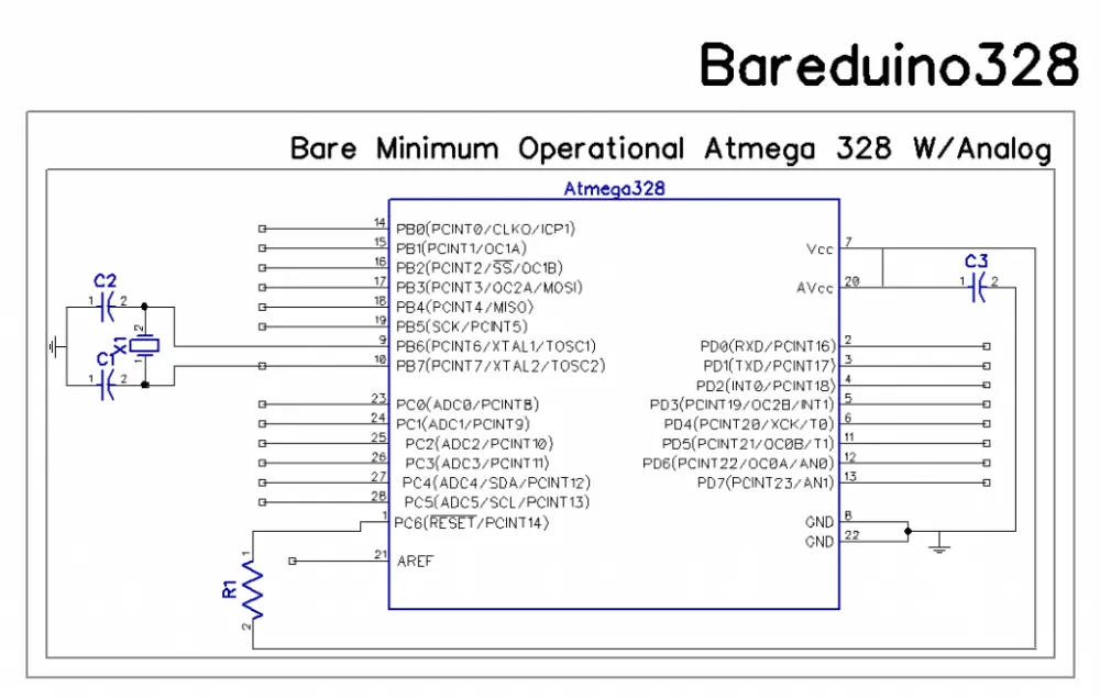
This article restores two Virtuabotix guides for the Bareduino328 — a bare ATmega328P wired up on a breadboard as a minimal, low-cost Arduino-compatible microcontroller. The first guide builds the base Bareduino328; the second, the Bareduino328 Plus, adds the parts and steps needed to regulate its own power rail.
Bareduino328: Building your Barebones Microcontroller
Posted on February 29, 2012 by Joseph Dattilo, in guides.
Description:
Need lots of Arduino Compatible controllers, but don’t need the price tag of a full development platform? This handy little kit is perfect for anyone who is experienced with the Arduino Compatible Micro-controllers, and needs to include a lot more of them in his/her next project. If you follow the steps on this page making a project on a breadboard is a snap, tie as many ATMEGA328’s together as you need to. The sky is the limit, and you don’t have to buy in bulk to get a great deal!
Package Contents:
- 1 x P-DIP ATMEGA328P-PU programmed with Duemilanove Bootloader
- 3 x Through-Hole 22pF Capacitors (2 for crystal and 1 for Analog power smoothing)
- 1 x Through-Hole HC-49S 16 MHz Crystal (for clock)
- 1 x Through-Hole 1/4 Watt 22 K ohm resistor (for reset pullup)
Note: Breadboard and wires are not included in the Bareduino and Bareduino Plus kits.
Optional but handy:
- 1 x Through-Hole 1/4 Watt 1 K ohm resistor (for an LED)
- 1 x Through-Hole 5mm LED (for Blink)
Key Features:
- Lower the cost and size of your next project
- Ideal for minimalistic deployments
- easily tie multiple controllers together to perform more complex tasks than possible with a single Micro-controller
The Setup
The process to making your first micro-controller come to life can be quite involved, even for someone with a little experience under there belt. To make the process less of a headache, we have provided this easy to follow guide. Follow the steps in this guide and your Bareduino will be up and running in no time!
The following items are needed for construction of your Bareduino (programmer method and parts in separate section).
- A Bareduino kit (Bareduino or Bareduino Plus)
- Breadboard
- Jumper wires
- Grounding strap (chip is ESD sensitive)
NOTE: This is a diagram of a 170-hole mini-breadboard. It is not drawn to scale.
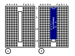
Step 1.) Details Get a breadboard, any old bread board will do the job as long as it is at least as big as this one. Power rails are nice, but since not everyone has them, this guide uses the most basic possible approach. (The breadboard pictured here comes with our Arduino Compatible Prototyping shield)
Step 2.) Details Time to open up that fancy ESD bag and pull off the Atmega328 chip. Put pin one (where the inset dot is in the bottom left corner of the chip) snug against he bottom left of the board. Make sure that the chip strattles the empty area in between the holes. If you don’t do this your chip will definitely not work because the left and right side of the chip will be tied together, causing much sadness.
Insert a red (positive) wire from a-9 to a-17. Insert a red wire from b-10 to b15. Insert a green (ground) wire from i-15 to i-17. Insert a green wire from j-7 to j-15.
Insert the 1/4 W (or whatever wattage you want) 22K Ohm resistor from a-1 to a-7.
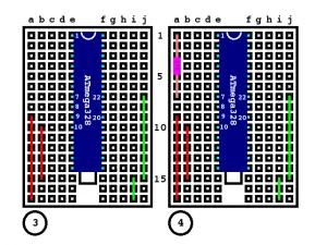
Step 3.) Details Place your power (Vdd) and ground wires as shown (green wires are ground, and red wires are power 5 Volts for most setups).
Step 4.) Details Put the 22K pullup resistor between pin 1 and the Vdd (red wire). This keeps the device from resetting continuously.
Insert the 16MHz crystal oscillator from c-15 to c-17. Insert a 22pF capacitor from e-15 to f-15. Insert a 22pF capacitor from e-17 to f-17.
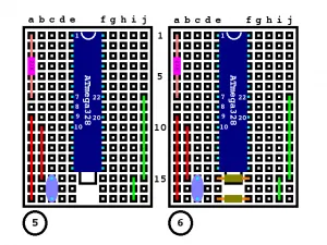
Step 5.) Details Connect the crystal pins to the rightmost two power bus lines.
Step 6.) Details Connect two of the three 22pF capacitors as shown in the image on the right. Each should connect to one of the crystal pins and the other connects to ground. This is what keeps the crystal running smooth.
Insert a 22pF capacitor from i-7 to i-9. Insert a red wire from b-7 to g-9.
Insert an LED from h-10 (positive side of LED) to h-16 (negative side of LED). Insert a 1/4 W (or any other wattage really) 1 K ohm resistor from g-15 to g-16.
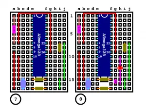
Step 7.) If you plan on using the Analog ports you will want to regulate the supply to them with the third Capacitor as seen in the image below.
If you don’t put this in your analog ports will not be powered at all.
The 3rd 22pF Capacitor serves to help regulate the AVCC line and keeps your analog data clean. Later if you put a larger cap on your VCC you can technically get rid of that capacitor (as long as you are powering it using VCC).
Step 8.) Optional It probably makes sense to add the LED and resistor for testing your Bareduino out now. Connecting as illustrated above should have you ready to load your first sketch as soon as you finish the next step.
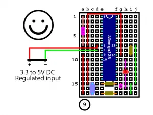
Connect the red wire from d-7 to the positive terminal and a green wire from d-8 to the negative terminal of a 3.3 to 5V regulated supply.
WARNING: USING HIGHER VOLTAGES CAN DAMAGE YOUR ATMEGA328, AND IS LIKELY TO MAKE WHOEVER DOES IT SAD.
Congratulations, you have finished wiring a Bareduino 328.
Special thanks go out to K.W. Melvin for contributing those awesome diagrams used above, I really appreciate you sharing them with the community.
When referencing pins on the ATMEGA328 the following pin-out diagram can be invaluable, be sure to compare against it (keeping in mind that pin 1 in next to the circular notch in the corner). (The original ATMEGA328P-PU pin-out diagram referenced here was not recoverable from archive — see sources.md.)
Already built yours? There is a Programming guide for taking this further. Checkout all of the other guides for the Bareduino328 series and please let us know if there is anything else you need to know.
Bareduino328 Plus: Regulate your Bareduino!
Posted on March 31, 2012 by Joseph Dattilo, in guides.
Description:
The Bareduino328 Plus brings you everything the Bareduino328 does with the added bonus of including what you need to regulate your power rail and keep your Bareduino’s running smooth. Just one Bareduino328 Plus can be used t0 power several other Bareduinos or other five volt devices.
Package Contents:
- 1 x P-DIP ATMEGA328P-PU programmed with Duemilanove Bootloader
- 3 x Through-Hole 22pF Capacitors (2 for crystal and 1 for Analog power smoothing)
- 1 x Through-Hole HC-49S 16 MHz Crystal (for clock)
- 1 x 5 Volt regulator (peak current 2 A, nominal) (L7805ACP — Input Voltage = 7.5 to 18 V, Output Voltage Low 4.8 Volts Nominal 5 Volts High 5.2 Volts)
- 1 x 22 uF Capacitor (to stabilize power rail during rapid current draw)
Key Features:
- Lower the cost and size of your next project
- Ideal for minimalistic deployments
- easily tie multiple controllers together to perform more complex tasks than possible with a single Microcontroller
- Greatly simplifies the process of adding power to your device, and allows user to safely draw greater current if needed
(The original product/circuit-diagram images for this section were not recoverable from archive — see sources.md.)
How to make your first Bareduino328 Plus:
First follow all of the directions to make a Bareduino328, once you have finished just follow the steps in this guide to get things rolling on your new device.
The Setup
The following items are needed for construction of your Bareduino328 Plus.
- Bareduino 328 Plus kit (Built initially as a Bareduino328)
- Breadboard
- Jumper wires
- Grounding strap (chip is ESD sensitive)
Step 1.) (photo “Step1 change Capacitor Positions” not recoverable — see sources.md) Move the ground end of the two Crystal Capacitors to the ground port on pin 8 as shown in the image to the left. Be careful to not let the crystal lines touch each other (through the capacitors).
Step 2.) (photo “Step 2 move ground line” not recoverable) Remove the extra tiny ground wire from where the Crystal Capacitors had been, and place the end of the long ground cable (green) one spot over to the middle of the three pins that used to be used for the Crystal capacitors (as shown in the image to the right).
Step 3.) (photo “Step 3 Insert Voltage Regulator” not recoverable) Insert the Voltage regulator being careful to ensure that the device is facing the same way as in the image to the left. The voltage regulator will burn out if you attempt to place the supply voltage on the wrong side of the chip!
Step 4.) (photo “Step 4 Tie Chip to Vout” not recoverable) Place a power wire from the furthest right pin to the chips power rail (pin 7). As long as the Regulator was inserted with the chip type and serial number facing you the Voltage In (VIN) will be on the left most pin, the Ground should always go to the middle pin, and he Voltage Out (Vout/Vdd) will be on the rightmost pin.
Step 5.) (photo “Step 5 Insert Brownout Protection Capacitor” not recoverable) Place 22 uF Capacitor between the Ground and Voltage Output pins to provide brownout protection in case there is a momentary increase in current draw that exceeds the ability of your supply or regulator.
NOTE: BE SURE TO ORIENT YOUR CAPACITOR CORRECTLY! (Reference photo below, and be sure to contact us if you have any questions). Failure to place the capacitor with the correct polarity can result in damage to you or your Bareduino. (The “Always ensure that your Capacitor is polarized correctly!” reference photo was not recoverable.)
Step 6.) (photo “Step 6 insert supply lines” not recoverable) Connect the Voltage Input and Supply Ground Pins as shown by the long red and green wire respectively in the image to the right.
Step 7.) Connect the power and ground to a DC power supply and rejoice!
Already built yours? There is a Programming guide for taking this further. Checkout all of the other guides for the Bareduino328 series and please let us know if there is anything else you need to know.
Restored from the josephdattilo.com/Virtuabotix archive — original publish dates preserved for each section. Text reproduced word-for-word from the archived Wayback Machine captures; see sources.md for the full provenance and a list of images that could not be recovered.
I'm Joseph Dattilo — engineer-founder in Lansing, Michigan, author of the FleetHarbor suite, and founder of Date Palm Media. More about me · More writing · Get in touch