
Virtuabotix BT2S Bluetooth-to-Serial: Master and Slave configuration and pinout

The BT2S line is Virtuabotix’s Bluetooth-to-serial module, sold as a Master (auto-pairs to a Slave) and a Slave (pairs to a Master or a PC/phone terminal). This article restores both halves of the documentation: the Master’s printed pinout/getting-started guide, and the Slave’s web guide — which is the one with the full AT command reference and the auto-config Arduino sketch.
BT2S Master — Bluetooth to Serial
Reproduced from the printed BT2S Master pinout guide (Virtuabotix LLC, copyright 2011–2012).
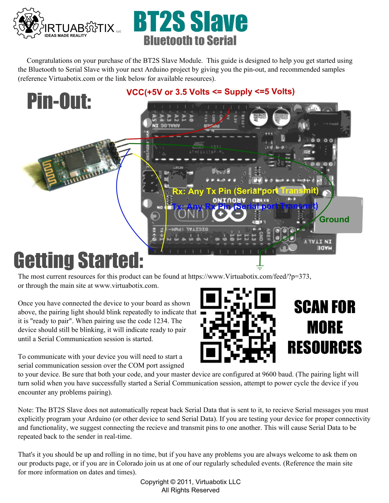
Congratulations on your purchase of the BT2S Master Module. This guide is designed to help you get started using the Bluetooth to Serial Master with your next Arduino project by giving you the pin-out, and recommended samples (reference Virtuabotix.com or the link below for available resources).
Pin-Out:
- Ground
- VCC (+5V or 3.5 Volts <= Supply <= 5 Volts)
- Rx: Any Tx Pin (Serial port Transmit)
- Tx: Any Rx Pin (Serial port Transmit)
- State Pin: (it blinks) — use to detect connection
- Key Pin: used for config/control
Getting Started:
The most current resources for this product can be found at https://www.Virtuabotix.com
Once you have connected the device to your board as shown above, the pairing light should blink repeatedly to indicate that it is “ready to pair”. The Master module is designed to automatically pair with a Slave Module and is mean’t to create an automatically linking pair for serial communication.
Once the device has paired the light will stop blinking as an indicator. To communicate with your device you will need to start a serial communication session over the COM port assigned to your device. (The pairing light will turn solid when you have successfully started a Serial Communication session, attempt to power cycle the device if you encounter any problems pairing).
It is also possible to connect the Master (or Slave) module to a Software Serial port to allow USB communication to be used for transmission of commands or data via a computer that is then transmitted to the distant end device.
That’s it you should be up and rolling in no time, but if you have any problems you are always welcome to check out our ever growing list of resources at www.virtuabotix.com, or submit a support request if we haven’t answered your question yet. If you are in Colorado join us at one of our regularly scheduled events and learn even more. (Reference the main site for more information on dates and times).
BT2S Slave — configuration and pinout
Posted on January 16, 2014 by Joseph Dattilo, in guides — reproduced word-for-word from the archived web guide.
Setting up your BT2S-Slave
Using a Hyper-terminal program
BT2S Slave is configured to operate at 9600 Baud with a Pin of 1234 right out of the box, but it can be configured in the following way:
First power up the device and connect it to a serial port that you can use Hyperterminal or an equivalent Serial Communication software. Remember you need to have the device in seek mode while configuring it (make sure it is not paired while trying to change the configuration). Configure your Hyperterminal to the baud rate you have your device set to (in this case 9600).
IMPORTANT NOTE: The commands must be entered very quickly, so it is suggested that you type the command into a text editing program and copy/paste into the terminal program to make configuring your device easier.
Send the command “AT”, and the device should return “OK”. If not check your Hyperterminal configuration and make sure the device isn’t paired.
To change the PIN code send the device “AT+PIN####” <- replace #### with your four digit pin.
To change the Baud rate send the device “AT+BAUD#” <- replace # with the BAUD code from the look up table below (keep in mind you will have to change your Hyperterminal Baud to that Baud rate if you want to continue to command the device).
To change the device name send the device “AT+NAMExxxx” <- Where xxxx is the new name.
| CODE | BAUD |
|---|---|
| 1 | 1200 |
| 2 | 2400 |
| 3 | 4800 |
| 4 | 9600 (Default) |
| 5 | 19200 |
| 6 | 38400 |
| 7 | 57600 |
| 8 | 115200 (MUST BE SELECTED MANUALLY, OVER SERIAL PORT) |
Generally you don’t need to change the parity from the default of None, but if for some reason you need to interface with a device that has a parity set you will need to know how to change that too.
To change the parity send the device “AT+Px” where x = N for None, E for Even, or O for Odd. The device will return “OKsetparity” on success (don’t forget you will have to change your com port settings after that).
Connected to a Versalino/Arduino
Now if you don’t want to go through all the trouble of programming by hand and you have a Versalino or Arduino handy, we came up with a way of making the changes with a program for the Arduino IDE.
First edit the code below to reflect the setup you want (for the moment 115200 and BT2S units that have been configured to 115200 must be configured directly with serial commands from the previous section):
This new program is fully automated, just change the desiredBaud and desiredPin at the top and the rest will automatically find the proper baud and setup your device to work as you desire.
int statusLED = 2; //the pin you connect your status LED to
int desiredBaud = 4;//index of your desired baud rate 4 is 9600
char* desiredPin = "1234";//change to the pin of your choice
unsigned int baudLookup[] =
{
1200, //code 1
2400, //code 2
4800, //code 3
9600, //code 4
19200, //code 5
38400, //code 6
57600 //code 7
};
void setup()
{
 pinMode(statusLED, OUTPUT);
 digitalWrite(statusLED, HIGH);
 //this block of code searches every possible baud rate until a
 //working rate is found (blinking briefly between searches)
 int myBaud = 1;
 while(!checkBT2Sstatus(myBaud)) {
 digitalWrite(statusLED, LOW);
 myBaud++;
 delay(200);
 if(myBaud > 7) myBaud=1;//reset baud and keep searching
 digitalWrite(statusLED, HIGH);
 }
 //blink fast to show baud found
 for(int i =0; i <10; i++)
 {
 digitalWrite(statusLED, LOW);
 delay(100);
 digitalWrite(statusLED, HIGH);
 delay(100);
 }
 delay(1000);//wait a second
 //blink number that corresponds to baud
 for(int i =0; i <myBaud; i++)
 {
 digitalWrite(statusLED, LOW);
 delay(200);
 digitalWrite(statusLED, HIGH);
 delay(500);
 }
 digitalWrite(statusLED, LOW); //we found the baud, now to configure
 //this is where you put your desired configuration
 // startingBaud newBaud PIN
 if(!configureBT2S(myBaud, desiredBaud, desiredPin))
 {
 digitalWrite(statusLED, LOW);
 while(true);//device failed to configure
 };
 digitalWrite(statusLED, HIGH); //SUCCESS!
}
void loop()
{
 digitalWrite(statusLED, LOW); //fast blink means success
 delay(200);
 digitalWrite(statusLED, HIGH);
 delay(200);
}
boolean configureBT2S(uint8_t startingBaud, uint8_t endingBaud, char* myPin)
{
 boolean myReturn = false;
 digitalWrite(statusLED, HIGH);//our device is attached and configured correctly
 delay(500);
 Serial.print("AT+PIN");
 Serial.print(myPin[0]);Serial.print(myPin[1]);Serial.print(myPin[2]);Serial.print(myPin[3]);
 delay(1500);//give it half a tick just to be sure its ready
 while(Serial.available()>0)Serial.read();//clear the buffer
 Serial.print("AT+BAUD");
 Serial.print(endingBaud, DEC);
delay(1500);//let it reset
if(checkBT2Sstatus(endingBaud)) myReturn = true; //final check
return myReturn;
}
boolean checkBT2Sstatus(uint8_t baud)
{
 Serial.begin(baudLookup[baud-1]);//pulls baud from baudLookup
 delay(500);//give it half a tick just to be sure its ready
 while(Serial.available()>0)Serial.read();//clear the buffer
 delay(1500);//wait for reset to complet
 Serial.print("AT");//checks to see if BT2S is connected, and set to proper baud
for(int i = 0;Serial.available()<2 && i <100; i++ ) delay(12);//give as much as 1.2 seconds for a response
if(Serial.read()=='O' && Serial.read()=='K') return true;
else return false;
}
Having Problems?
If you have any problems whatsoever please let me know by either calling and leaving a message, making a Technical support request, or simply emailing/messaging me either directly or via Amazon.
Open source
The BT2S auto-config sketch above (and its slave/master pairing test programs)
are on GitHub as arduino-bt2s-tools
(Apache-2.0) — the auto-config sketch reproduced above (BT2S_AUTOCONFIG_V1S1A)
and the BT2S-Slave test/programmer sketch used during manufacturing test.
There was never a general-purpose BT2S Arduino library (no .h/.cpp
class) — the AT-command approach above is the whole interface — so this is a
tools collection, not a library in the DHT11/Ultrasonic sense.
Restored from the josephdattilo.com archive — original publish date preserved. The Master section is reproduced from Virtuabotix’s printed pinout guide (never captured live by the Wayback Machine — see sources.md); the Slave section and code are word-for-word from the archived web guide.
I'm Joseph Dattilo — engineer-founder in Lansing, Michigan, author of the FleetHarbor suite, and founder of Date Palm Media. More about me · More writing · Get in touch